Replacing your Front End Processor Scope
This document highlights how Microsoft SNA Server installed on the Barr Enterprise Communications Server may act as a primary gateway for remote TCP/IP and SNA devices. It explains the benefits enabled with this configuration as compared to a similar implementation on an IBM Front End Processor or other Plug Compatible Manufacturer Front End Processor.
Although we understand that there may be many applications involved with or using a Front End Processor, the comparisons made herein focus on the single application of SNA mainframe access.
The end of this document details different configurations and sample definitions by which to implement SNA gateway functions.
Introduction
Front End Processors (FEPs) are specialized hardware platforms designed to offload IBM mainframes of communications functions. Over the years, users have adopted them as the primary physical access platform for communication to the mainframe.
IBM announced that it has discontinued hardware maintenance, in North America, for certain older models of FEPs effective January 31, 1999. This will force many IBM customers to find replacements for that hardware. IBM suggests several solutions that involve purchasing additional IBM hardware.
With the paradigm shift of network processing and processor pricing, and the discontinuation of certain FEP hardware, it is the goal of this paper to highlight how to implement a relatively inexpensive but elegant hardware and software solution to provide similar services and improve performance over traditional architectures.
Front End Processors
FEPs are so called because they 'front end' the connections between networks and mainframe processors. They came into being as an important tool to reduce overhead of doing teleprocessing "busy work" on the mainframe processor. FEPs were initially designed to be inexpensive to install and maintain in order to reduce using the higher priced CPU cycles of the mainframe processor.
Front End Processors were engineered to provide common functions needed to attach terminals, printers and other devices to a mainframe computer through communication lines. They typically channel attach to the mainframe via channel interfaces and communication circuits via Line Interface Cards. They transmit and receive messages, assemble and disassemble packets and detect and correct errors.
The software that controls the FEP and defines what exactly is attached to the FEP is the Network Control Program (NCP). The NCP is customized and created on the mainframe and loaded into the FEP. The customization of the NCP for a particular configuration of communication lines and attached devices is a highly detailed oriented process and requires the talent of a highly trained programmer.
FEPs have grown and matured in function since their inception. They now perform many 'backbone networking' functions such as routing, transport and network functions of the SNA architecture that were not even conceived when FEPs were introduced. Many larger IT shops implement multiple FEPs with these features to enable wider support of their SNA or backbone network. The FEPs also perform a service known as "boundary function." Boundary function includes such services as converting network address to local addresses, polling of remote devices and providing session level pacing. These functions occur at the edge or boundary of the network.
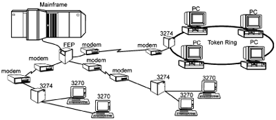
The most common devices attached to FEPs are typical SNA 3270 type terminals and printers. These are attached to 3274/3174 control units that are then attached to the FEP. IBM 3274/3174 Control Units are specialized processors designed to provide communication line functions on behalf of attached or downstream terminals.
Figure 1 depicts a Front End Processor connecting two 3274 control units and a Token Ring LAN to a mainframe host.
Figure 1 - Front End Processor
FEP Cost of Ownership
Boundary functions were the primary reasons giving rise to the FEP. However, as requirements emerged to support larger and more complex SNA networks, the platform of choice for implementation of these solutions was the FEP. As functionality of the NCP software became more complex and feature rich, the Total Cost of Ownership (TCO) has risen accordingly. Conversely, with the advent of newer CMOS and alternate mainframe processing technology, the price per MIP (Millions of Instructions Per second) of mainframe processors has decreased dramatically.
In reviewing TCO of an FEP, two of the primary considerations are one-time charges and recurring charges. The one-time charge includes purchasing of the hardware and licensing of the NCP software. A somewhat more intangible yet very real expense, that should be factored into the TCO equation, is the time spent by the systems programmer on training and installation of the FEP hardware and NCP software. Recurring charges are the associated monthly or yearly maintenance fees for the hardware and software, upgrade charges and salaries of associated support personnel.
As a rule, any changes that need to be performed on the FEP need to be performed in an 'offline' mode. Off-line refers to the state of being deactivated from the host operating system and access method, Multiple Virtual System (MVS) and Virtual Telecommunications Access Method (VTAM) as an example. In the last few years improvements to MVS and VTAM allow updating of the NCP software while online to the mainframe. For hardware however, addition, moves or changes still should be performed while the FEP is off line. The taking of an FEP offline can negatively impact many connected users and hence occurs very infrequently, and then only at off hours to lessen the impact to business users.
A Barr Alternative
Barr Systems has assembled a system that supplies many of the same functions of a boundary function FEP, with increased performance and in most instances at a much lower price. In some installations the system could actually replace FEP configurations entirely. This system is the Barr Enterprise Communications Server, which includes Microsoft SNA Server, BARR/CHANNEL with Bus & Tag or ESCON and BARR/SYNC for SNA Server products.
For configurations that contain primarily boundary functions, i.e. 3270 terminals and printers with 3174 control units attached by SDLC or 802.2/DLC LAN to an FEP, the Barr Enterprise Communications Server can be used as a replacement for the FEP.
Barr Enterprise Communications Server
Barr Enterprise Communications Server is a pre-configured, custom built, enterprise-networking solution that enables high-speed seamless integration of mainframe, Internet and intranet networking resources. Barr Enterprise Communications Server implements BARR/CHANNEL with Bus & Tag or ESCON adapters for the highest speed mainframe access available, Microsoft SNA Server, Microsoft Windows NT and all of the latest Client/Server and Web access software available, built into the latest Intel processor technology based server.
This system will use BARR/CHANNEL adapters for host attachment and BARR/SYNC, high-speed synchronous adapters, for communication line attachment. Microsoft SNA Server software provides the necessary communications functions in the Barr Enterprise Communications Server.
Microsoft SNA Server
Microsoft SNA Server is a software product that enables a PC or Workstation appear to an IBM mainframe host as one or more 3x74 control units with attached 3270 type terminals and printers. Microsoft SNA Server supports SNA Physical Unit Type 2 (PU2) and Physical Unit Type2.1 (PU2.1), with Logical Units 1, 2 or 3 (LU1, LU2 or LU3). It also supports Downstream Stream Physical Units (DSPU). DSPU is the attachment of real 3x74 control units or other MS SNA Servers to this (mainframe attached) Barr Enterprise Communications Server by communication links. Communication links supported are SDLC, X.25 (QLLC), Frame Relay, Token Ring, Ethernet, and ATM.
BARR/CHANNEL for SNA Server
BARR/CHANNEL for SNA Server provides high-speed attachment of SNA Server to an IBM mainframe computer using parallel (Bus & Tag) or serial (ESCON) channels. They are available in PCI bus versions. Parallel channels support channel speeds of 4.5Mbps and serial channels support speeds of 17Mbps.
BARR/SYNC
BARR/SYNC adapters provide for the attachment of synchronous devices at speed up to 2.048 Mbps using SDLC, Frame Relay or X.25 protocols. They are available in PCI bus version. These adapters are used to communicate with the downstream control units or other downstream Barr Enterprise Communications Server. The BARR/SYNC adapter supports DATMODE=FULL, which enables true full-duplex communications on SDLC data links.
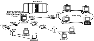
Figure 2 shows a Barr Enterprise Communications Server replacing the Front End Processor. Notice the architecture of the network remains unchanged.
Figure 2 - Barr Enterprise Communications Server
Reliability
The IBM FEP is a very reliable device, grown in the mainframe arena out of the need to provide high quality, uninterrupted service to a large organization or enterprise. To insure uninterrupted service IBM offers a maintenance service agreement that provides for short turn around time for repair or replacement of the FEP. IBM (or other providers) will stock commonly needed repair parts either locally or at a parts depot. FEPs also have the capability of operating in various modes to provide redundancy and backup functions. One configuration is where the 3745 is logically 'split' into two discrete operating environments independent of the other half of the processor. When utilizing this function, 50% of the FEP resources are unused and are 'lying in wait' for a failure situation. In effect they are spare parts in warm standby mode.
Servers on the other hand grew out of the Client-Server arena where reliability was not the ultimate requirement. While they are not known for their reliability, the industry is realizing that reliability is key for servers to flourish in the Enterprise IT market. However, they are relatively inexpensive and it is common and economically feasible to have spare parts or entire spare systems stored on-site, ready to be used in the event of system failure. To insure continuous operation, there are a number of things that may be done to help an organization achieve that goal. Microsoft SNA Server has the capability to have numerous systems active and configured in such a way so as to allow one SNA Server to 'back-up' another server's sessions. This is a designed function of SNA Server that implements another form of hot or warm standby. Another strategy that should be employed is to stock at least one replacement unit of each component of the system, including communication boards, modems, cables, and normal server components such as disk drives.
Performance
One aspect of the performance of the Barr Enterprise Communications Server is that by being channel attached using ESCON, messages from the attached nodes are being passed to the mainframe using channel speeds of 17Megabytes per second. Channel attaching communications nodes is the most efficient and fastest means available for transferring data to and from a mainframe. When comparing performance of Barr Enterprise Communications Server with Microsoft SNA Gateway to an FEP/NCP, it is important to again compare 'apples to apples.'
A channel-attached FEP/NCP may have data to send to the mainframe on behalf of a number of resources located throughout an Enterprise. This data may be destined for any number of applications, having a different 'Class of Service' associated with each packet, and ranging in size from 128 bytes up to potentially ~4000 bytes or more. All of these characteristics have an impact on overall performance and channel accessibility. This data all has to compete for channel resources for mainframe access.
With Barr Enterprise Communications Server with SNA Server channel attached to the mainframe, the demand for channel resources at the server level may be lessened by some degree than when using an FEP. Usually, most data has the same type of characteristics when using Barr Enterprise Communications Server with SNA Server - same frame/packet size and same class-of-service. Having the same data model decreases the work the processor has to perform to put the data on the channel.
If the workload destined for the Barr Enterprise Communications Server is a significant amount, multiple BARR/CHANNEL adapters and BARR/SYNC adapters may be configured to increase the overall bandwidth configured for Barr Enterprise Communications Server processing. With each BARR/CHANNEL having the ability to support channel speeds of 17MegaBytes per second, and BARR/SYNC supporting full-duplex speeds of up to 2.048MegaBits per second, the Barr Enterprise Communications Server is a powerful and totally scalable solution that can grow with your processing requirements.
Capacity
Barr Enterprise Communications Server can be configured with up to four BARR/CHANNEL adapters and four BARR/SYNC adapters. Each channel card can support up to eight or more control unit definitions and each control unit definition can support up to 254 LUs. This yields a total capacity of over 8,000 host sessions. Each SDLC card can support four downstream devices, each with 254 LUs. This yields a total of 4,064 downstream LUs. The 4,064 remaining host connections can be distributed with network-attached downstream units.
Costs - Barr Alternative Costs
When comparing implementation costs of the different access alternatives, it is important to truly compare 'apples to apples.' Since every organization's configuration is different, it is impossible to provide comparative pricing examples for every configuration. We can however provide some items to consider when evaluating strategies.
One-time costs, for a Barr Systems implementation of typical boundary function-like services, would be the purchase of a late model Intel powered server with large amounts of memory, BARR/CHANNEL hardware, Microsoft SNA Server software (pricing starts for five client support), and one or more BARR/SYNC network interface adapters. You will need to license Microsoft SNA Server and a client license for each LU in your configuration. Implementation of this system requires experienced technical support staff, but mainframe systems programmers' time is minimal. Barr Systems also can supply a fully installed, configured, and tested system to your organization that is basically plug-and-play. This would lessen the demand on your own internal IT staff. To ensure continuous operation, you may want to stock a spare of each hardware component. The only continuing costs would be the optional Annual Service Agreement or Annual Licensing Agreements to cover maintenance on the Barr Enterprise Communications Server.
Implementation and ongoing expenses of an FEP/NCP would entail the FEP Purchase Price and an optional Hardware Maintenance Plan (charged monthly, quarterly or annually). The NCP software must be purchased and licensed separately. In some instances there is an annual licensing fee for the software. Add to that the annual software maintenance fee for any new features and fixes.
Although configurations may vary greatly, the Barr Systems' Solution is very cost-effective when compared to other high-end implementations supplying the same type of functionality.
Determining if you are a candidate for this product
Table 1 shows some communication protocols you might be using in your FEP and how they are supported in the Barr Enterprise Communications Server.
Table 1 - Barr Enterprise Communications Server support for communication protocols
Binary synchronous communication (BSC) |
Support will be available in the future |
Ethernet-type LAN |
802.3 attached devices are supported |
Frame relay |
Frame relay at speeds up to 2.048Mbps are supported |
IBM special products or user-written code |
Not supported |
Synchronous Data Link Control (SDLC) |
SDLC connected 3274 type control units are supported at speeds up to 2.048 Mbps |
Start-stop |
Asynchronous devices are supported with Windows NT RAS |
Token ring |
4M and 16M token ring is supported |
X.25 |
X.25 is supported up to 2.048Mbps |
Table 2 shows the type of devices that may have been previously FEP attached and that now may be attached via the Barr Enterprise Communications Server.
Table 2 – Barr Enterprise Communications Server support of attached devices
Point to point or multi-point SDLC attached 3174 and 3274 control units |
Up to 4 lines supported with up to 16 control units and thousands of sessions |
A link attached Front End Processor |
Not supported. You may be able to replace the downstream FEP with another Barr Enterprise Communications Server which would be supported |
Channel or SDLC connections to multiple mainframe |
While multiple mainframes can be connected to a single Barr Enterprise Communications Server and each can access some of the configured control units, the connection cannot be used for SNA Network Interconnection (SNI) connections between mainframes |
PU 2.1 |
Supported with PU Passthrough |
Technical Details
Various options are available for connection of down stream 3270 control units. They include Downstream PU, PU Passthrough and Distributed Link Service.
Figure 3 - Downstream PU  |
PU Passthrough
PU passthrough also allows attachment of 3270 control units to SNA Server. In this case the LUs are not mapped by SNA Server and appear directly on the host definition for the control unit. A significant difference between DSPU and PU Passthrough support is that with PU Passthrough the individual LUs are not defined on the Barr Enterprise Communications Server and they can not be queried or controlled from the Barr Enterprise Communications Server. To determine the status of an LU you must query it from the host.
To allow for the FEP replacement with a Barr Enterprise Communications Server to be as transparent as possible to Computer Operations personnel and end users define the Passthrough control units in VTAM with the same PU and LU names as their current NCP definitions.
PU Passthrough must be used when the downstream device will be a PU2.1 node.
Distributed Link Service (DLS)
DLS can be used when the downstream control unit is SNA Server emulating a 3274. It allows the upstream SNA Server to provide access to a host link service to the downstream SNA Server. A significant advantage of DLS is that the downstream devices can be attached with non-SNA communication protocols.
Table 3 shows a summary of the features supported by these three downstream device attachment options.
Table 3 - A summary of downstream attachment services
|
PU Passthrough |
Downstream PUs |
Distributed Link Service |
Allows connection of real 3274 control units |
Yes |
Yes |
No |
Allows LUs on a single host defined PU to be shared between control units |
No |
Yes |
No |
Allows downstream SNA Servers without direct host attachment to communicate with host |
Yes |
Yes |
Yes |
Downstream PUs appear as distinct channel addresses on host |
Yes |
Maybe |
Yes |
Appears to host as a channel attached SNA control unit |
Yes |
Yes |
No |
LUs are defined on SNA Server and may be queried and controlled |
No |
Yes |
No |
VTAM requires a logmode table entry to match the device type of the 3274 control unit, either remotely attached (SDLC) or channel attached. This may require the use of different logmode table entries than were used with the NCP.
Configuring your connections
For each 3270 control unit you are configuring, you will need to find the following values from your NCP definition: IDBLK, IDNUM, MAXDATA, NRZI, and ADDR. Table 4 shows how these fields are entered in the corresponding configuration fields in Barr Enterprise Communications Server.
Table 4 - Mapping NCP parameters to Barr Enterprise Communications Server configuration fields
| NCP Macro |
NCP parameter |
SNA Server resource |
Tab |
Field |
Field use |
Switched Major Node PU |
IDBLK & IDNUM |
Connection |
System Identification |
Local Node ID |
Used for both switched SDLC connections and LAN connections |
PU |
MAXDATA |
Connection |
SDLC |
Max BTU Length |
Size of the largest Path Information Unit (PIU) the control can receive |
Line |
NRZI |
Connection |
Address |
Encoding |
Select NRZI if NRZI=YES and NRZ if NRZI=NO |
PU |
ADDR |
Connection |
Address |
Poll Address |
Used for SDLC connections |
N/A |
|
Connection |
General |
Remote End |
Select Downstream for DSPU or PU Passthrough |
N/A |
|
Link Service |
Mode Settings |
Line Type |
Leased or appropriate version of switched |
N/A |
|
Link Service |
Mode Settings |
Constant RTS |
For maximum performance select this unless it is on a multidropped line |
N/A |
|
Link Service |
Mode Settings |
DATMODE = FULL |
For maximum performance always select this |
Line |
Speed |
Link Service |
Card Configuration |
Common Parameters/Data Rate |
Set this value if the modem is NOT supplying the clocking. (NCP Clockng=int) |
When converting connections from an NCP to Barr Enterprise Communications Server the mainframe definitions for the control units move from the NCP to SNA Major Nodes. Each control unit must now be defined in VTAM as a Local PU and twice in Barr Enterprise Communications Server, once in the channel connection and again in the SDLC connection. In the VTAM Major node that defines the control units, each must be assigned a unique subchannel address. You can obtain these from your mainframe systems programmer and use them in configuring Barr Enterprise Communications Server.
Figure 5 shows a sample of the necessary VTAM major node definition. These previously NCP-attached control units are now attached via Channel E and carry subchannel addresses 44 and 45. These VTAM definitions would be the same whether they are on the same SDLC connection in BEPS (making them multidropped) or different connections.
Figure 5 - Sample VTAM configuration
*
* 3174 Connection via Channel Attached Barr Enterprise Print Server
*
VBUILD TYPE=
LOCALCE4LNT00PUCUADDR=E44,DISCNT=NO, +
ISTATUS=ACTIVE, +
DLOGMOD=SNX32702, +
MODETAB=MTBARR, , +
USSTAB=BARRTAB, +
MAXBFRU=48, +
PUTYPE=2, +
VPACING=0, +
PACING=0
*
TE4LNTOO LU LOCADDR=
2
TE4LNT01 LULOCADDR=
3TE4LNT02 LU
LOCADDR=
4. . .
*3174 Connection
viaChannel Attached
BarrEnterprise Print Server* VBUILD
TYPE=
LOCALCE5LNT00PUCUADDR=E45,DISCNT=
NO, + ISTATUS=
ACTIVE, + DLOGMOD=
SNX32702,
+ MODETAB=
MTBARR, +USSTAB=BARRTAB, +
MAXBFRU=48, +
PUTYPE=2, +
VPACING=0, +
PACING= 0
*TE5LNT00 LU
LOCADDR=
2TE5LNT01 LU
LOCADDR=
3
TE5LNT02 LU LOCADDR=4
. . . |
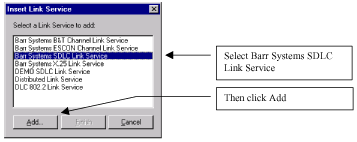
After initially installing SNA server you can configure it will just a few simple steps. Here is how to configure a multi-dropped PU Passthrough configuration. Right-click on Link Services and select Insert/Link Service.
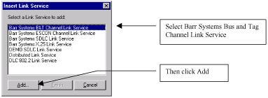
The configuration dialog uses a tabbed interface. The Link tab allows you to select the BARR/CHANNEL adapter card to use. The pull down list will show all installed adapters with their serial number. Since the serial number is visible on the back of the card it is easy to select the right one.
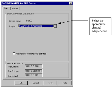
Traditionally, mainframes expect all the physical units on a channel to be powered on before the channel is varied online. When a channel is varied online, the mainframe polls each of the units it expects to find on this channel. If a unit does not respond, an error message displays on the operator console.
To respond to the mainframe poll, the BARR/CHANNEL device driver must know the subchannel address. Usually this information is not available until you start the corresponding SNA Server connection and the connection reaches the pending state. However, you can use the Static Subchannel Addresses feature to predetermine which addresses the BARR/CHANNEL with ESCON device driver should respond to, so the driver can respond to the poll when the connection is inactive.
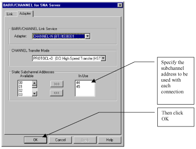
If you have installed more than one channel adapter in the machine you repeat this process until they are all installed.
Next you add the Link Services for the SDLC cards, one for each card. Right-click on Link Services and select Insert/ Link Service.
In the next dialog you will be presented with a pull down menu of all the SDLC cards for BARR/SYNC installed in the machine. You must add a Link Connection for each of them.

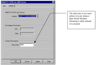
Repeat the Link Service Add process until you have defined all the SDLC adapters for BARR/SYNC that are installed.
You are now ready to define the connections. Right-click SNA services and select Insert/ Connections/ Channel.
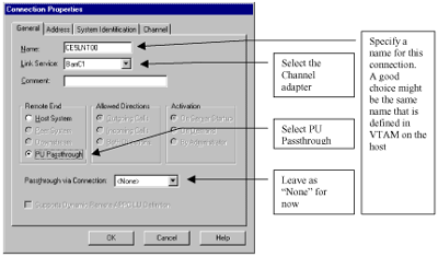
Each control unit must have a unique subchannel address. This value is independent of the SDLC polling address the device uses.
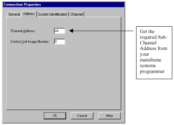
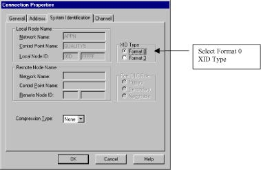

Add a Channel Connection for each downstream control unit, each with its own subchannel address.
Now are ready to add the SDLC connections. Right-click SNA Service and select Insert/Connection/SDLC.
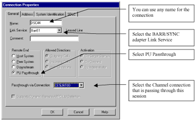
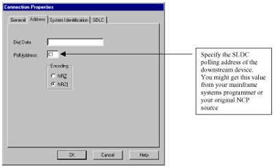
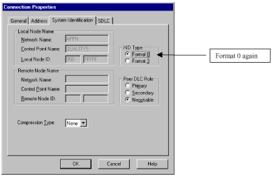
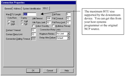
Add an SDLC Connection for each downstream control unit. You can define multiple connections per SDLC Link Service if you are using multi-dropped devices.
When all of your configurations are complete and the cabling is connected you are ready to activate Barr Enterprise Communications Server. Make all of the downstream devices active, then start the SNA Services on Barr Enterprise Communications Server then ask the mainframe operations personnel to vary active the VTAM major node(s) containing the control unit definitions.
Conclusion
The Barr Enterprise Communications Server can be used as a cost-effective replacement for a Front End Processor. Using Barr's high-speed mainframe channel attachment and synchronous communication attachments with Microsoft's SNA Server, Barr Enterprise Communications Server provides high-performance connection of 3270 control units, terminals and printers to IBM mainframes at a considerable cost savings over alternatives. This can be accomplished with no changes from the end user's perspective and little change from the mainframe operations personnel perspective. |

